
CADclips Announces New $19, $39 and $99 REVIT Video Training Tutorial Subscriptions

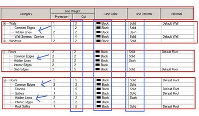
Figure 'A'
Have you even noticed the 'Object Style' Sub-category 'Common Edges' and 'Hidden Lines' and wonder "What the %$^# they are there for" ?
See Figure 'B' below.
These 'Common Edges' and 'Hidden Lines' sub-categories show up in the 'Objects Styles' all over the place in many system families.
Have you ever wished you could fine tune the line weights or patterns of the 'internal layers' of a wall, floor or roof etc ?
Well here's the poop.
Well here's the poop.
The 'Common Edges' are the lines between the 'Layers' within a wall, or floor, or roof or ceiling structure. See Figure 'A' above.
The outer edges of the walls, floors etc take on the cut style of the main category 'Wall' or Floor' etc. The internal lines are the 'Common Edges'.
Figure 'B'
Having said that enter . . . . . the override. . . . .
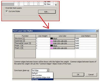
Yes the Visibility Graphics Override (per view) can fine tune those 'common edges' by checking the 'Cut Line Styles' option and click the 'Edit' button. See Figure 'C' below.
So with the 'common edges' sub-category and visibility graphics overrides you can really fine tune the appearance of the internal layers of walls, floors, roofs, ceilings etc. In section or plan.
Figure 'C'
Now, the 'Hidden Lines' sub-category is different.
It is used to display edges of elements that have been told to show as 'Hidden' when behind a particular element. See Figure 'D' below.
Use the 'Show Hidden Lines' tool from of the View tab of the ribbon.
Pick the object to do the 'hidding' then pick the object to 'show as hidden'. The hidden lines then take on the appearance of the line style and weight specified in the sub-category 'Hidden Lines'. This tool can also be used with a combination of both model and detail objects in plan, elevation, section and 3D views !
Figure 'D'
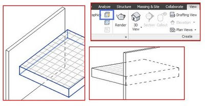
Figure 'D'
In the image above the wall was told to be hidden by the floor
and the floor was told to be hidden by the wall.
Gotta run . . . .. . . .
2 comments:
I can't believe you posted this today. I've been working on a problem for weeks & last night somebody figured it out for me using the "cut line styles".
I do architectural and structural coordination within the same revit file. I wanted structural wall assembly layers to show in structural views without showing the architectural layers of the same wall.
"Cut line styles" was perfect - I just set assembly layers that I didn't want to show to "white" and "phantom" line style.
Thanks for the hints!
Nice article & interesting timing for me.
Last night someone taught me how to hide external layers of a wall as well.
I do architectural and structural coordination within the same revit file. I always wanted to hide the non-structural layers of a wall assembly in my structural views without splitting up the wall assemblies.
The "cut line styles" and "override host layers" was the answer. I just changed the color and line style of layers I wanted to hide to "white" and "phatom" line style.
So now we can not only control the appearance of interior wall layers, but we can control the visibility of exterior wall layers as well!
If only I could make this work for structural 3d views...
Post a Comment