Below are 4 CADclips on how to create a very slick Stepped Footing family.
A family that will get used many times !


This blog is provided for All Things REVIT.
The CADclip below demonstrates how to use the new REVIT 2011 Keyboard Shortcuts Interface.
Looks like they finally caught up to the AutoCAD interface . . . oops did I say that out loud. . . (you have always been able to edit the keyboardshortcuts.txt file . . .right)
 Then we change the framing members in the truss type properties as shown in the two images below.
 Here's the poop:
 Temporary Dimensions
Revit now remembers edits to temporary dimension witness lines per session. Once you tweek a temporary dimension on an object it remembers that tweek during the editing session.
Temporary Dimensions
Revit now remembers edits to temporary dimension witness lines per session. Once you tweek a temporary dimension on an object it remembers that tweek during the editing session.
 Adaptive Components
Adaptive component functionality is designed for situations when components need to flexibly adapt to unique contextual conditions. Adaptive points are created by modifying reference points. The geometry drawn by snapping to these adaptive points results in an adaptive component.
Adaptive Components
Adaptive component functionality is designed for situations when components need to flexibly adapt to unique contextual conditions. Adaptive points are created by modifying reference points. The geometry drawn by snapping to these adaptive points results in an adaptive component.
 Form Editing
A form can be edited in sketch mode by modifying the curves from which it was created. A form can also be dissolved back to the curves from which it was created. Once a form has been dissolved, its profile curves and path (when applicable) remain. These curves and path can be edited to create a new form.
The Dissolve Form command removes the surfaces from a form, leaving the valuable defining profiles, curves and points.
Form Editing
A form can be edited in sketch mode by modifying the curves from which it was created. A form can also be dissolved back to the curves from which it was created. Once a form has been dissolved, its profile curves and path (when applicable) remain. These curves and path can be edited to create a new form.
The Dissolve Form command removes the surfaces from a form, leaving the valuable defining profiles, curves and points.
 Large Team Workflow
Improve your ability to work with projects containing linked files with the capability to apply view filters, tag elements, and control visibility of worksets.
Large Team Workflow
Improve your ability to work with projects containing linked files with the capability to apply view filters, tag elements, and control visibility of worksets.
 Text Improvements
Improvements to text tools enable you to:
Adjust the location of the leader relative to the text block
Format text with bullets and numbering
Modify text using the Find & Replace Text tool
Text Improvements
Improvements to text tools enable you to:
Adjust the location of the leader relative to the text block
Format text with bullets and numbering
Modify text using the Find & Replace Text tool
 Structural Tools
Several structural tools, previously available only in Autodesk® Revit® Structure software, are now available to Autodesk Revit Architecture users.
These tools include:
Curved Beams
Metal Decking
Slanted Structural Columns
Trusses
Beam Coping tool
Beam System Tags
Structural Tools
Several structural tools, previously available only in Autodesk® Revit® Structure software, are now available to Autodesk Revit Architecture users.
These tools include:
Curved Beams
Metal Decking
Slanted Structural Columns
Trusses
Beam Coping tool
Beam System Tags
 Enhanced Visualization
Autodesk Revit Architecture now provides the ability to display materials and ambient lighting in editable views.
Enhanced Visualization
Autodesk Revit Architecture now provides the ability to display materials and ambient lighting in editable views.
 Keyboard Shortcuts
Autodesk Revit Architecture now provides a new interface for managing keyboard shortcuts for Revit Tools.
Add or remove keyboard shortcuts and assign multiple shortcuts for each Revit Tool.
Import keyboard shortcuts from another user.
Export keyboard shortcuts to share them with other users, or to a spreadsheet program where you can sort, organize, and print a list of shortcuts for quick reference.
Keyboard Shortcuts
Autodesk Revit Architecture now provides a new interface for managing keyboard shortcuts for Revit Tools.
Add or remove keyboard shortcuts and assign multiple shortcuts for each Revit Tool.
Import keyboard shortcuts from another user.
Export keyboard shortcuts to share them with other users, or to a spreadsheet program where you can sort, organize, and print a list of shortcuts for quick reference.
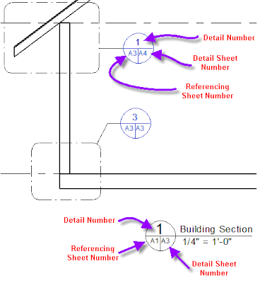
 Custom Elevation Tags
Define the appearance of view tags used for elevations. Elevation tags can now have any shape and any number of arrows pointing in nonorthogonal directions relative to the tag body.
Custom Elevation Tags
Define the appearance of view tags used for elevations. Elevation tags can now have any shape and any number of arrows pointing in nonorthogonal directions relative to the tag body.
 Background Images in Rendered View
Autodesk Revit Architecture now provides the ability to display images in the background of rendered views.
Background Images in Rendered View
Autodesk Revit Architecture now provides the ability to display images in the background of rendered views.
 Sheet Improvements
Improvements to sheets enable you to:
List sheets on the drawing list that are not in the project, such as consultant drawings
Consistently align views on sheets.
Sheet Improvements
Improvements to sheets enable you to:
List sheets on the drawing list that are not in the project, such as consultant drawings
Consistently align views on sheets.
 Convert Line Types
The convert lines tool converts existing model lines, detail lines, and symbolic lines into the preferred line type.
Convert Line Types
The convert lines tool converts existing model lines, detail lines, and symbolic lines into the preferred line type.
 Repeat Last Command
Revit 2011 makes it easy to repeat the command that was last used, or select from a list of recently usedcommands
Repeat Last Command
Revit 2011 makes it easy to repeat the command that was last used, or select from a list of recently usedcommands
 Reporting Parameter
Let's you create a parameter that is easily usable in other families and schedules such as reporting the wall thickness in a door or window schedule.
More Information
Key Features Common to all Revit Platform Software Autodesk® Revit® Architecture 2011, Autodesk® Revit® MEP 2011 and Autodesk® Revit® Structure 2011 software share a common set of key enhancements for improved design functionality and workflow to help design teams accelerate better design with tools that promote productivity and support sustainable design and analysis. See the Autodesk® Revit® Platform Enhancements for 2011 backgrounder for information on the platform enhancements.
Enhancements specific to Revit Architecture 2011 include:
Form Editing:
Sketch editing for conceptual masses in Revit Architecture 2011 has been improved with the ability to edit individual profiles of any type of form without having to delete the form first, similar to “sketch mode” but even more accessible.
The Dissolve Form command removes the surfaces from a form, leaving the valuable defining profiles, curves and points.
In the past, only voids could be used as cutting elements for Boolean operations, and it was difficult to access them again for further transformations. Now solids can be used to cut other solids, so that when the cut is executed, geometry from both forms remains visible.
Surface Rationalization:
The ability to rationalize surfaces has been enhanced. Surfaces can now be split by levels, reference planes and model lines.
Now, divided surface patterns can be made up of any combination of UV grids and intersects created by these new elements.
Adaptive Components:
The adaptive component is a generalized implementation of the pattern-based curtain panel family, which was introduced with the 2010 release of Autodesk Revit Architecture. It is designed to handle cases where components need to flexibly adapt to many unique contextual conditions. The adaptive component can be used to simply fill in the empty edge panels on a divided surface or for more complex modeling or framing applications.
Structural Tools:
Several features formerly available only in Autodesk Revit Structure software are now available in Autodesk Revit Architecture, such as the ability to create:
Curved beams
Slanted columns
Beam copings
Trusses
Metal deck profiles, and more
Rendering Enhancements:
Background Images Revit Architecture now provides the ability to display images in the background of rendered views.
Procedural Textures Create custom procedural textures based on patterns such as checker, gradient, wood or tiles.
New Autodesk Material Library More smoothly exchange material data between Autodesk applications with the new Autodesk Material Library. Materials can be exchanged with certain other supporting Autodesk applications (AutoCAD®, Autodesk® Inventor®, Autodesk Revit MEP and Autodesk Revit Structure software) in a true one-to-one mapping — helping create a consistent definition and rendered look and minimize the need to rework materials after data import.
Note: The new Material Library in Revit Architecture 2011 will only export materials, lights, or environments to 3ds Max/3ds Max Design 2011.
Removal of Four-Core Rendering Limit Rendering in Revit-based products is no longer limited to the use of four cores on multiprocessor computers. Revit-based products can now take advantage of as many cores as are available on your computer.
Access to Autodesk® Green Building Studio® Web-Based Services (Available with Subscription to Revit Architecture)
More smoothly extend BIM workflows to include sustainable analysis. With more than 1.6 million virtual weather locations across the globe, the climate information used in analyses can be more local, accurate and current.
By using the power of cloud computing, Green Building Studio can generate analyses in a matter of minutes, thus helping architects and designers to iterate through multiple design options earlier and more often.
For new buildings projects, whole building energy analysis can help predict more accurate building operation costs before construction. For renovation and retrofit projects, the software helps users to make the most efficient design choices.
Reporting Parameter
Let's you create a parameter that is easily usable in other families and schedules such as reporting the wall thickness in a door or window schedule.
More Information
Key Features Common to all Revit Platform Software Autodesk® Revit® Architecture 2011, Autodesk® Revit® MEP 2011 and Autodesk® Revit® Structure 2011 software share a common set of key enhancements for improved design functionality and workflow to help design teams accelerate better design with tools that promote productivity and support sustainable design and analysis. See the Autodesk® Revit® Platform Enhancements for 2011 backgrounder for information on the platform enhancements.
Enhancements specific to Revit Architecture 2011 include:
Form Editing:
Sketch editing for conceptual masses in Revit Architecture 2011 has been improved with the ability to edit individual profiles of any type of form without having to delete the form first, similar to “sketch mode” but even more accessible.
The Dissolve Form command removes the surfaces from a form, leaving the valuable defining profiles, curves and points.
In the past, only voids could be used as cutting elements for Boolean operations, and it was difficult to access them again for further transformations. Now solids can be used to cut other solids, so that when the cut is executed, geometry from both forms remains visible.
Surface Rationalization:
The ability to rationalize surfaces has been enhanced. Surfaces can now be split by levels, reference planes and model lines.
Now, divided surface patterns can be made up of any combination of UV grids and intersects created by these new elements.
Adaptive Components:
The adaptive component is a generalized implementation of the pattern-based curtain panel family, which was introduced with the 2010 release of Autodesk Revit Architecture. It is designed to handle cases where components need to flexibly adapt to many unique contextual conditions. The adaptive component can be used to simply fill in the empty edge panels on a divided surface or for more complex modeling or framing applications.
Structural Tools:
Several features formerly available only in Autodesk Revit Structure software are now available in Autodesk Revit Architecture, such as the ability to create:
Curved beams
Slanted columns
Beam copings
Trusses
Metal deck profiles, and more
Rendering Enhancements:
Background Images Revit Architecture now provides the ability to display images in the background of rendered views.
Procedural Textures Create custom procedural textures based on patterns such as checker, gradient, wood or tiles.
New Autodesk Material Library More smoothly exchange material data between Autodesk applications with the new Autodesk Material Library. Materials can be exchanged with certain other supporting Autodesk applications (AutoCAD®, Autodesk® Inventor®, Autodesk Revit MEP and Autodesk Revit Structure software) in a true one-to-one mapping — helping create a consistent definition and rendered look and minimize the need to rework materials after data import.
Note: The new Material Library in Revit Architecture 2011 will only export materials, lights, or environments to 3ds Max/3ds Max Design 2011.
Removal of Four-Core Rendering Limit Rendering in Revit-based products is no longer limited to the use of four cores on multiprocessor computers. Revit-based products can now take advantage of as many cores as are available on your computer.
Access to Autodesk® Green Building Studio® Web-Based Services (Available with Subscription to Revit Architecture)
More smoothly extend BIM workflows to include sustainable analysis. With more than 1.6 million virtual weather locations across the globe, the climate information used in analyses can be more local, accurate and current.
By using the power of cloud computing, Green Building Studio can generate analyses in a matter of minutes, thus helping architects and designers to iterate through multiple design options earlier and more often.
For new buildings projects, whole building energy analysis can help predict more accurate building operation costs before construction. For renovation and retrofit projects, the software helps users to make the most efficient design choices.
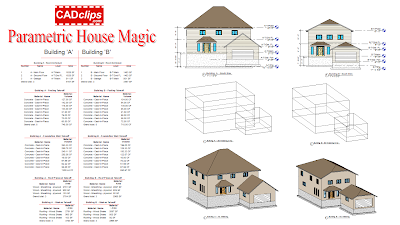
 This family tutorial will teach you some cool stuff about nested families, parameters and also save you a ton of time if you ever need to label room sizes.

 REVIT does not come installed with a title block family parameter that displays how many sheets are in a sheet set. In fact REVIT doesn't have sheet sets.
 Here's the new way to create a 'Curtain System by Lines'.


Most people can create a good material takeoff and or quantity schedule in REVIT and get totals and grand totals. But bridging the gap to costing and the almighty $ sign is tricky.
For many regualr 'schedules' all you have to do is add in a 'cost' as part of the instance or type parameters. But 'material takeoff's' are a little different.
If you create a foundation 'material takeoff' schedule that tells you that you have 1500 cubic feet (CF) of 'cast in place concrete' and you know your cost is $15 / CF then you should be able to formulate that overall cost. But you will run into a road block > error: Inconsistant Units
The problem occurs when you try to use the 'currency' unit (dollar) and the 'volume' unit (CF) together in the same REVIT schedule field formula. You will get an 'Inconsistant Units' error.
The answer is to create an intermitant variable that translates the volume unit to real number units. Then multiply that number by the cost / unit and Bob's your uncle.
For 30+ free REVIT Lab Exercises go to this post > CADclip Labs
Set the Pixel width to 720p for HD video quality.
Here's the CADclip.
 Did you know you can edit the 'header' information in REVIT Schedules and 'Group' (or ungroup) columns as indicated above?


 So we know the Adjacent (12) and the user inputs the Opposite (Rise) but the trick is we have to use the 'Inverse Tangent' to get the actual angle in degrees. Otherwise all we get is the Tan of the angle, not the actual angle itself. So the correct term for Inverse Tan is ArcTan which REVIT accomodates as the built in operator atan.


