Monday, July 18, 2011

REVIT 2012 View Control Bar


Above is the 2011 Visual Style button.
2012 has removed the 'Shaded' option (that no one ever used anyway).


With the Release of REVIT 2012 we see some modifications to REVIT's 'View Control Bar'. Outside playing musical chairs with the 'Grapic Diplay Options' I like it. 
This post describes some of those changes.

Above is the 2012 Visual Styles button where 'Shaded with Edges" has become 'Shaded'. Then we also see that the 'Graphics Display Options' dialog box has been added here.


Above we see that 2012 has also moved the 'Graphics Display Options' to the View's Properties (where it should be).
Above we see the 2011 'Shadows' button.
Now it's just a toggle On / Off and the 'Graphics Display Options' has been relocated to two other locations described in this post.
Above we see the 2012 Shadows Toggle. On or Off. Thank you !
Above we see the new, awesome 2012 Lock 3D view option for annotation purposes.
If you are in the default {3D} view it will prompt you to duplicate the view.
Last we have the wonderful 2012 WorkSharing Display and settings !
WAIT FOR IT !!


Saturday, July 16, 2011

REVIT and ICF and IntegraSpec


This wall system has REVIT Architecture, Structure and more importantly REVIT MEP written all over it !!

REVIT Generated, Carbon Footprint Data.


I have started using ICF (Insulated Concrete Forms) for more than just foundations. This wall system is fantastic for the entire building envelope. It also works well with the Hambro Floor and Roof system.

IntegraSpec® (pronounced >  integra . . . spec) is an innovative building system that builds stronger, safer, quieter, energy efficient and environmentally friendlier homes and structures.

IntegraSpec® is “The User Friendly ICF” TM is produced in Canada, USA and also 2 plants in Europe.

Their unique and patented design makes it the easiest and most versatile Insulated Concrete Wall System on the market today.


I should be offering a few ICF / REVIT tips over the coming months.

Below are some more images and details.


Thursday, July 14, 2011

REVIT Common Edges and Hidden Lines

CADclips Announces New $19, $39 and $99 REVIT Video Training Tutorial Subscriptions

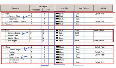
Figure 'A'

Have you even noticed the 'Object Style' Sub-category 'Common Edges' and 'Hidden Lines' and wonder "What the %$^# they are there for" ?

See Figure 'B' below.

These 'Common Edges' and 'Hidden Lines' sub-categories show up in the 'Objects Styles' all over the place in many system families.

Have you ever wished you could fine tune the line weights or patterns of the 'internal layers' of a wall, floor or roof etc ?

Well here's the poop.

The 'Common Edges' are the lines between the 'Layers' within a wall, or floor, or roof or ceiling structure. See Figure 'A' above.

The outer edges of the walls, floors etc take on the cut style of the main category 'Wall' or Floor' etc. The internal lines are the 'Common Edges'.

Figure 'B'

Having said that enter  . . . . . the override. . . . .
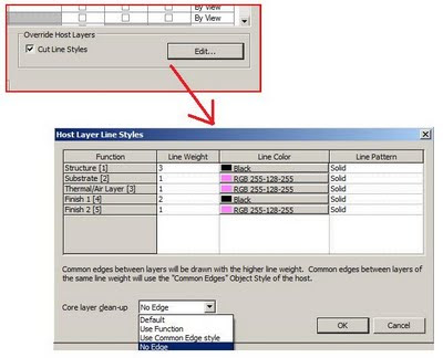
Yes the Visibility Graphics Override (per view) can fine tune those 'common edges' by checking the 'Cut Line Styles' option and click the 'Edit' button.  See Figure 'C' below.

So with the 'common edges' sub-category and visibility graphics overrides you can really fine tune the appearance of the internal layers of walls, floors, roofs, ceilings etc. In section or plan.

Figure 'C'

Now, the 'Hidden Lines' sub-category is different.
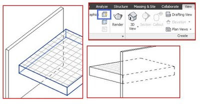
It is used to display edges of elements that have been told to show as 'Hidden' when behind a particular element. See Figure 'D' below.

Use the 'Show Hidden Lines' tool from of the View tab of the ribbon.
Pick the object to do the 'hidding' then pick the object to 'show as hidden'. The hidden lines then take on the appearance of the line style and weight specified in the sub-category 'Hidden Lines'. This tool can also be used with a combination of both model and detail objects in plan, elevation, section and 3D views !


Figure 'D'

In the image above the wall was told to be hidden by the floor
and the floor was told to be hidden by the wall.

Gotta run . . . ..  .      .         .

Wednesday, June 29, 2011

REVIT Section Head Bubble CADclip


As shown above you can offer a variation of section head bubbles in
REVIT Architecture, Structure and MEP.

View the CADclip below to learn the best way to modify a REVIT Section Head Bubble.

You can also use this exact same method to change the Section Tail Symbol.


Friday, June 24, 2011

REVIT 2012 Roof Cricket CADclip


Below is a great little CADclip on how to create a roof cricket around a roof pentration.


In the CADclip above we use the normal roof edge slope methods and 2 very small edges.

You can also accomplish this cricket by using two 'Slope Arrows' as shown in the image below.
In the image below I placed the 2 slope arrows along the gable end of the cricket pointing towards the middle of the cricket. Note that you do NOT need to split the roof footprint linework on the gable edge. The roof footprint is made up of 3 segments only. Then to set the slope properties select the slope arrow(s) and use the properties palette. You can modify both arrows at the same time.

Monday, June 20, 2011

REVIT Railing with Glass Panels


3D View of Railing Ballaster Panel Family Template
Ballaster Configuration Dialog Box Railing Configuration Dialog Box
Above are 4 images.

The top image is of the completed railings with one railing type for flat railings and one railing type for sloped railings.
Each railing type (flat and sloped) contains two railings, two end posts, 1" ballasters and 2'-0" wide glass panel 'ballasters'. Yes the glass panel is a ballaster !!

The second image is inside the new ballaster family template (Ballaster-Panel.rft).
Here we create and load two new ballaster panel families. Each ballaster panel family is made up of an extrusion 1/4" thick with 4 sides aligned and locked to the reference planes.

For the flat railing type, use the vertical and horizontal ref. planes.

For the sloped railing type, use the vertical and sloped ref. planes.

Make the extrusion material 'glass'.

After you load the two ballaster panel families into the project you can assign them to the new railing family.

Next we need to duplicate the 'Railing- Handrail -Pipe' family twice and rename them 'Glass Panel Rail Flat' and Glass Panel Rail Slope'.

The two new railing types will be identical other then specifying the sloped or flat ballaster panel.

The third image is of the Ballaster Placement dialog box found in the type properties of the railing.

Note the families and the numbers.

The forth image is of the Railing Structure dialog box found in the type properties of the railing.

Note the families and the numbers.
* From what I can tell, when working in the ballaster placement dialog box the 'distance from previous' is measured from the ballaster center lines.

*Also don't forget to set the ballaster 'Justify' to 'Spread Pattern to Fit'.

* You can set the panel width (2'-0" by default) in the type properties of the panel family listed in the project browser (double click).

The panel height is controlled by the ballaster placement dialog box. (top and base offset)

Detailed videos to be prodiuced on this topic process at:

CADclips REVIT Videos Here

Tuesday, May 31, 2011

Copy and Pasting REVIT Legends

Have you ever tried to 'Copy and Paste' a REVIT legend from a 'Sheet View' in Project 'A' to a 'Sheet View' in Project 'B' ?
It cannot be done or at least not from 'Sheet View' to 'Sheet View'. So how can you copy a legend from one project to the next ??
The answer is to 'Copy and Paste' all the elements from Legend View to Legend View. Not from Sheet to Sheet.
Once you have pasted the elemets into the Legend View of Project 'B' then you place that legend on a sheet.

Friday, May 13, 2011

REVIT Dormers Gone Wild !


Well today is 'Dormer' day in the REVIT training room and I thought I'd post some of the fun we are having.
I can't believe the how well these 12 people have progressed.


Wednesday, May 04, 2011

Daryl Gregoire Offers Live REVIT Training


 Daryl Gregoire is now offering

Live One on One REVIT Training
in Calgary Alberta, Canada.

Learn REVIT software from the Best of the Best
and launch your career into the BIM world of employment.

Don't delay !

Email Daryl Here

Thursday, April 28, 2011

REVIT 2012 Assemblies Training

Below is a CADclip overview on the new REVIT 2012 Assemblies (or Assembly) feature.
First you group elements into assemblies.
Then based on that assembly you can create views, sheets, isolate elements, schedule, tag, create material take offs and parts lists.
Have a look and you'll see what I mean.
Very Cool indeed !

Thursday, April 21, 2011

Revit 2012 - Rendering, Materials and Visual Styles

I am really enjoying REVIT Architecture 2012 and I need to dig into the new 'Parts' and 'Assemblies' features, which will take a little time, but in the mean time the new materials features combined with the new visual styles and ambient lighting really ROCK !


Thursday, April 07, 2011

REVIT CADclip In-Place Massing with Rachel Toon

Below Rachel Toon kicks off a video series on REVIT Architecture 2011 'In-Place Massing'. The series promises to teach curtain systems, panels, mullions, materials, rendering and more.

Tuesday, November 30, 2010

REVIT Wall with Reveal to Create a Planter

I had this question come up today and thought it would make a great tutorial.
Below is a 3 part CADclip series on how to use a wall and a built in reveal to create a Planter.

Friday, November 19, 2010

Wednesday, October 06, 2010

REVIT Server

Wow, I just like the sound of those words . . . . REVIT SERVER . . . . . yes in deed.
Just seems to naturally roll off the tongue.
This is going to 'open a few doors' . . . pun intended . . .
Autodesk has a new product coming out named 'REVIT Server' that uses a WAN and a web based administrative tool to access the 'central file' on the 'central server'. Then the central server manages and syncronizes the data to the local servers which deal with the local PCs.
After all, as everyone gets BIM'd up the next natural step is to be able to connect the models across a WAN for a geographically challanged, collaborative REVIT project.
Read more here.

Thursday, August 05, 2010

REVIT Flared Bottom Tread

Above your see the 3D and sketched plan view of how to make a flared the base tread of a tread in REVIT.